What is being built, how it works, and — the part most tuning pages leave out — what has not been proven yet. Nothing here is a product until it says it is.
Written as the work happens · Bench results included, good and bad
29 September 2026On the bench
Chasing a programming fault that nobody had root-caused
A thread on NefMoto this week: crossflash an ME7.5 and the ECU sets P0602, "control module programming error". It sticks through a key cycle. Nobody had a root cause, and the usual answer is an assembly patch that stops the code being logged.
It is a long-standing annoyance with no good explanation behind it, and the bench here has both ECU generations on it. Seemed worth pointing at. What follows is what fell out over about a day, some of it useful, some of it wrong.
Naming the thing
The function everyone was patching writes one of two constants, 0xA5F0 or 0x5A0F, into a word of RAM and reads it back later. An A2L for a related ECU names that word outright: Status der Flashprogrammierung: 0xA5F0 bedeutet Fehler, sonst fehlerfrei. Flash programming status, A5F0 means error.
So the patch that had been circulating was not disabling a check. It was forcing the clean value to be written every time.
A question that turned out not to be a question
Part of the thread was about why the A-chassis ECUs report P0602 while the B-chassis ones report P1681, and whether that was a chassis split or a generation split.
It is neither. Every fault path in these ECUs carries several code words as ordinary calibration constants — a customer code and a CARB code among them. For the flash-programming path:
CDKFLP (Kodewort Kunde) — four entries, all 0602 CDCFLP (Codewort CARB) — the same four, all 1681
Two different images from two different part numbers carry byte-identical blocks. P0602 and P1681 are the same fault with two names, and which one a scan tool shows depends on which set it reads. That closed off a line of investigation rather than opening one, which is still worth something.
Where the bench came in
The flag itself lives in the EEPROM, and it was already set in ECUs that had never been touched by the tool under suspicion. So the question became: why does one flasher leave it set and another not?
Same ECU, same file, same baud rate, two writes back to back. Nine fault codes one way, eleven the other, with P0602 only in the second. Then the EEPROM read out after each:
after the other tool 01 02 4E 45 46 4D 54 4F 80 2E 9C — flag set
after ours 01 02 01 00 00 00 00 00 00 2F A1 — flag clear
Six bytes in the middle of that record are the flash tool code, sent as a parameter in the erase request. The byte immediately after it is the flag. Whatever the ECU makes of that field, it decides the outcome.
Two wrong turns worth recording
The first guess was that verifying particular flash sectors cleared the flag and that our flasher happened to do it. That died when both tools turned out to verify the same nineteen sectors in the same order.
The second was that some intermediate probe was resetting progress. That died too, once a third tool code was tried and behaved like the first, which ruled out the sequence and pointed squarely back at the field contents.
Both were reasonable and both were wrong, which is roughly the normal ratio.
One thing that saves everyone time
Checking that flag had meant reading the EEPROM. It does not have to. The ECU returns it over K-line in a single request:
1A 9C → 5A 9C 80 2E 9C 00
flag byte, successful programming count, attempt count
Byte for byte the same as the EEPROM location everyone had been pulling chips to read. Our own flasher had been requesting it on every connection for months without anyone noticing what the first byte meant.
None of this is a UGTuner feature and none of it needs to be — our flasher never produced the fault. It is written up because the answer was worth having and nobody had it, and because a bench with two ECU generations on it is worth more pointed at a real problem than sitting idle.
28 September 2026On the benchNot in a release
Teaching a bench ECU that it has an engine
Most of what is left to prove on the flex and speed-density work needs the ECU's crank-synchronous code to be running. With nothing on the crank input it never starts, so an ignition angle sits still, injection is never scheduled, and half the interesting variables never change. That is why several bench sessions could only confirm that a number existed, not that it moved.
The fix was a 60-2 crank wheel generated by a microcontroller: fifty-eight teeth, two missing, driven as a differential pair through AC coupling because the ECU's input expects a variable-reluctance sensor rather than a logic level.
ECU read 300 and 1000 rpm against 300 and 1000 commanded
reference mark found, ignition angles computing normally
tracked cleanly to 8000 rpm
With that running, an ECU on a bench behaves enough like one in a car to answer questions that previously needed a car.
The first thing it answered
ME7.5 has a factory limp mode for a failed cam sensor: it fires each cylinder every 360 degrees instead of every 720, which is wasted spark, implemented by Bosch and present in every one of these ECUs. Enabling it is one codeword. That matters for engine swaps where no usable cam signal exists.
The flag that reports it is active was not in any definition file we had, and the A2L we did have gave an address that turned out to be wrong for this software — of 270 flags shared between that file and ours, 206 sit at different positions. Guessing would have produced a plausible-looking log channel pointing at nothing.
Instead: log the raw flag words, change the one codeword, run the same test again, and diff. One bit appears in the second run and in no sample of the first. A DAMOS obtained later agreed, independently, to the same word and the same bit.
The cam side, honestly
Simulating the cam sensor took three attempts. A single symmetrical window never synchronised, because these wheels have four windows of unequal width and the ECU reads the signal level at the reference mark to work out which revolution of the cycle it is on. A symmetrical pulse cannot express that.
The pattern was eventually measured off a scope capture of a real sensor and reproduced as a tooth table. It is close, not exact, and the tooth positions carry perhaps a degree of uncertainty. For the cam-less work that does not matter, which is the case the bench is actually for.
The wasted-spark side is proven on the bench and has not run on an engine. As with everything else here, it says so until it does not.
27 September 2026In the logger
A power curve from a log, with the word “estimate” left in
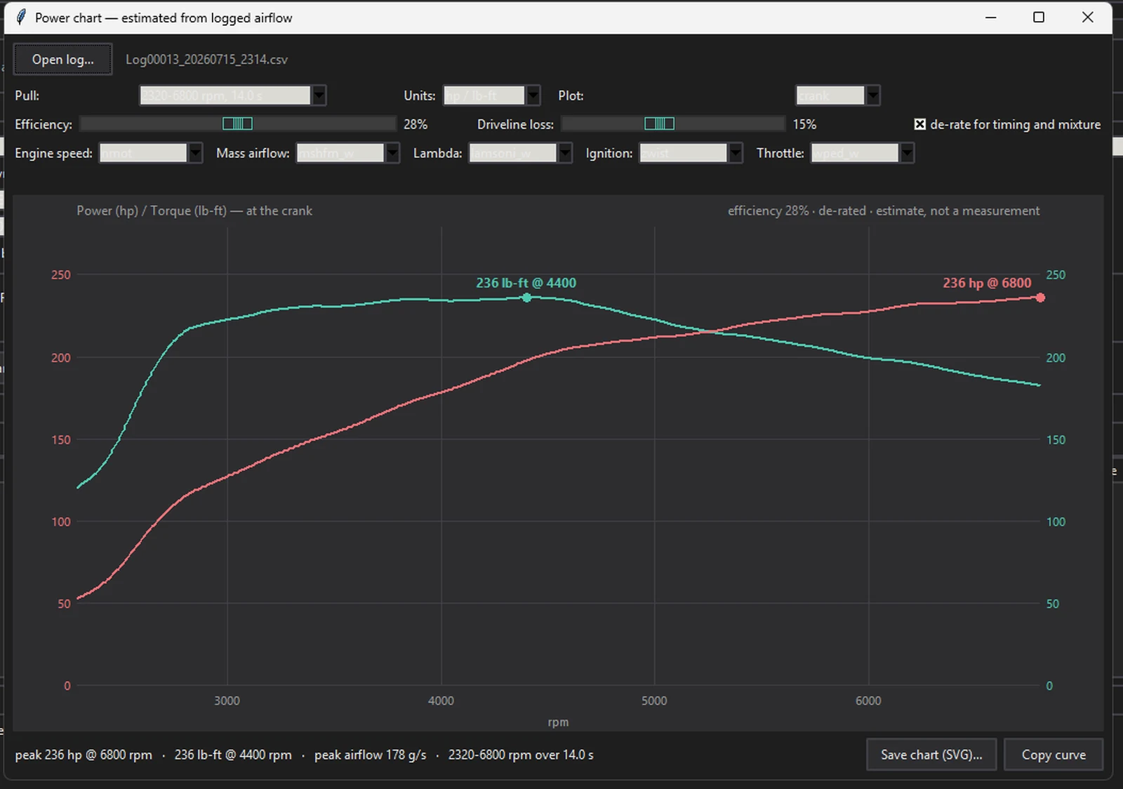
A dyno pull costs money and a booking. A third-gear pull on a quiet road costs nothing, and the ECU is already measuring the air going into the engine several hundred times a second. That is enough to draw a curve that is useful for tuning decisions, as long as nobody pretends it is a measurement.
Logger — Power chartEstimated from logged airflow
One third-gear pull, 2320 to 6800 rpm over fourteen seconds. The chart says what it is across the top, every time.
Airflow gives torque directly if you know how efficiently the engine is turning that air into work. The tool asks for that efficiency rather than guessing it, and then de-rates for the two things that most often make a log flatter than the engine really is: ignition pulled below optimum, and a mixture that is not where the tuner thinks it is.
That de-rate reads the measured channels, not the targets. Asking the ECU what lambda it wanted tells you nothing about what the engine got. On the pull above, using the target instead of the measurement would have moved the peak by a useful amount in the wrong direction.
What it is good for
Comparing two files on the same car — the errors are mostly constant, so the difference is meaningful even when the absolute number is not.
Finding where a curve stops climbing and whether that is the turbo, the fuel system, or a map.
Checking a dyno sheet against what the ECU thought was happening. That has already caught one sheet run in the wrong gear with the wrong drivetrain selected.
What it is not
It is not a dyno, and the window says so in three places on purpose. Efficiency and driveline loss are inputs, which means anyone can produce whatever number they want by moving two sliders. That is exactly why the figure belongs next to the assumptions that produced it rather than on its own in a screenshot.
24 September 2026On the benchNot in a release
Flex fuel for ME7.5: fuelling, ignition and cold start
Running E85 on an ME7.5 car usually means picking a blend and tuning for it. Put something different in the tank and the calibration is wrong until someone edits it again. A flex setup reads what is actually in the fuel and adjusts as it goes — which on these ECUs means adding code, not just changing maps.
This is the state of that work. It runs on the bench. It has not run on an engine.
Reading the sensor
A standard GM-style flex sensor sends ethanol content as a frequency and fuel temperature as a pulse width. An ESP32 converts that to a voltage the ECU can read on the downstream oxygen sensor input — an input most tuned cars have already stopped using.
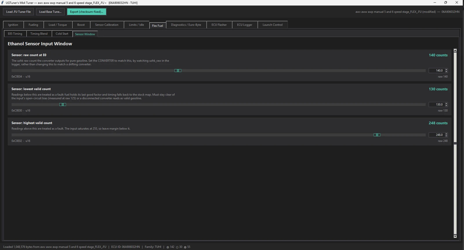
The mapping from that voltage to what the ECU actually sees was measured rather than assumed: a stepped sweep through the whole input range, logged from inside the ECU, giving a straight line with under one count of scatter and no hysteresis. The converter is then calibrated against that, not against a meter reading at the pin.
Flex Fuel — Sensor WindowE0 point · valid range
The valid window sits clear of both the input’s open-circuit bias and its saturation point, so a disconnected converter reads as a fault rather than as petrol.
Fuelling
Ethanol needs roughly half again as much fuel as petrol for the same air. The patch scales the ECU's own fuel constant continuously with ethanol content — 1.00× on pump gas up to 1.49× at E100.
That 1.49 is the real stoichiometric ratio, 14.70 against 9.86. The 1.40 figure often quoted is right for E70, which is what winter pump E85 frequently turns out to be — and not depending on what the pump claims is the entire point of fitting a sensor.
If the sensor fails, the patch holds the last good reading rather than reverting to petrol. Reverting is the common approach and it is backwards: the fuel in the tank does not change composition when a sensor dies, so fuelling for petrol with E85 in the tank runs 33% lean. The filter is asymmetric for the same reason — rising ethanol tracks quickly, falling ethanol lags, so it errs rich in both directions.
Ignition
Ethanol resists knock, so it will take more advance — but how much more is not a constant, it varies across the whole load and rpm range. The approach here is the one GM used on its own flex calibrations: two complete timing tables and a blend between them.
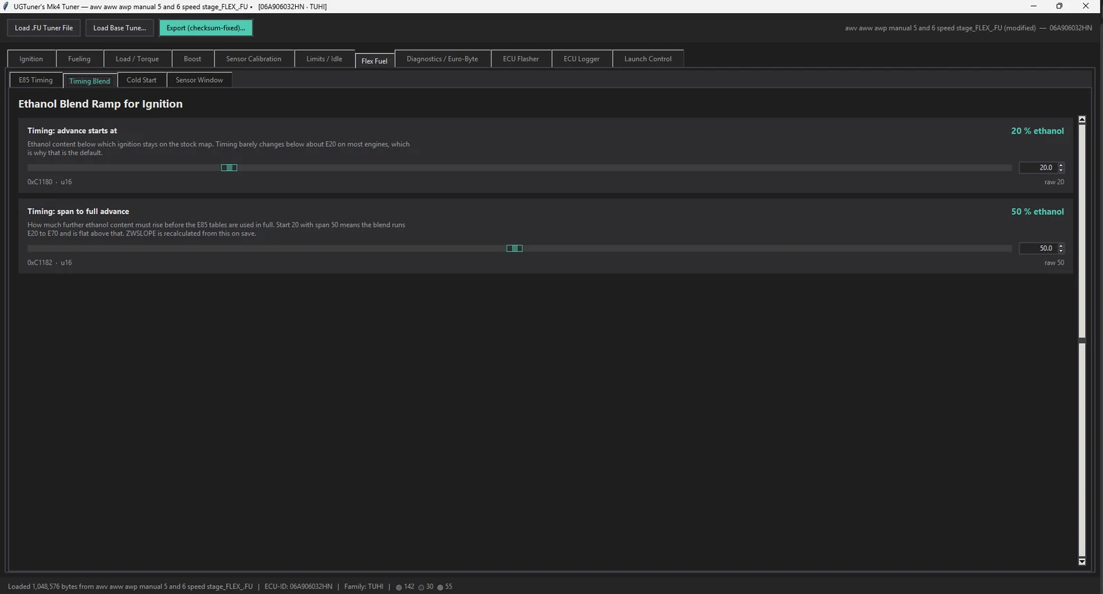
The stock tables stay exactly as they are and become the petrol tables. Two new E85 tables are added, and timing is blended between them by ethanol content along a ramp the tuner sets — typically nothing extra below E20, full advance by E70, since ignition stops changing much past the middle of the range.
Flex Fuel — Timing BlendRamp start · span to full advance
Where the blend starts and how far it runs. The patch’s internal slope constant is derived from these on save, so the two cannot be set inconsistently.
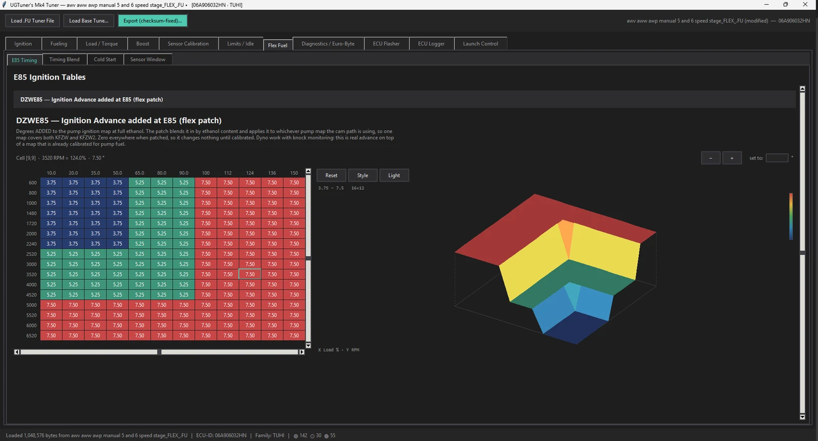
The new tables are written as copies of the stock ones, so a freshly patched file behaves identically to an unpatched one at every ethanol content until someone calibrates them on a dyno. Nothing happens by accident.
Flex Fuel — E85 TimingDZWE85 · 16 × 12 · ° added
Degrees added on top of whichever pump map the cam path is using, so one table covers both. Zero everywhere on a freshly patched file.
An earlier version reused the ECU's existing optimum-spark tables instead of adding new ones, which is tempting because it needs no extra space. It was dropped: the torque model reads those tables to work out how much torque the engine is making, so filling them with E85 numbers quietly shifts throttle response, idle control and the torque figure sent to the gearbox. Separate tables leave all of that alone.
Cold start
This is the part everyone warns about, and the old threads all describe the same failure: the engine fires cleanly, then dies the moment the throttle is touched in the first minute.
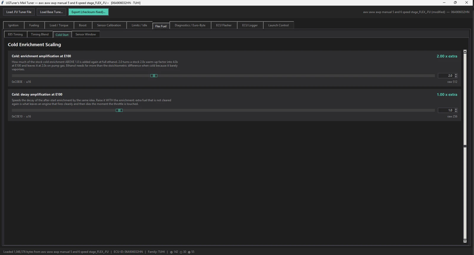
The cause is not a shortage of fuel. Ethanol barely vaporises when cold, so it needs far more enrichment than the stoichiometric difference — but enrichment that is not cleared again builds up in the intake and drowns the engine on the first throttle opening. So the patch scales both: the enrichment the calibration already has, and the rate at which it decays.
It scales what the factory maps already describe rather than adding new tables, so the temperature shape a tuner has already dialled in is kept, and it switches itself off the moment the ECU enters closed loop — no fighting with the fuel trims.
Flex Fuel — Cold StartEnrichment · decay
Two numbers, because both halves matter: more fuel when cold, and clearing it again quickly enough that the engine does not drown on the first throttle opening.
What the bench says
A fifteen-minute logged sweep across the whole ethanol range, checked against what the code should produce in every cell:
fuel constant tracked ethanol exactly — every plateau matched
base ignition moved −1.5° to +10.5° as ethanol rose
sensor disconnected → fuelling held, timing fell back to the petrol map
no faults, no dropouts, across 3,500 samples
Along the way the bench also caught a bug worth mentioning: the first version stored its state in a byte of RAM that the factory code reads a flag out of. It worked on the bench and would have quietly interfered with something else on a running car. It was found by checking every instruction in the firmware that touches that address, not by testing.
What is not done
No engine has run it. Everything above is bench work.
Cranking fuel is still stock; the after-start and warm-up phases are the ones handled so far.
Boost is untouched — ethanol will usually take more, and that is the next piece.
The E85 tables need calibrating on a dyno with knock monitoring. The patch provides the mechanism, not the numbers.
The editor side is already in place: the E85 tables, the blend ramp, the cold-enrichment scaling and the sensor window all live on their own tab, with the ramp's internal constant derived automatically so it cannot be set inconsistently.
Running E85 on an ME7.5 car in a cold climate and interested in being a test bed? Get in touch — the cold-start side in particular needs winter and a real engine, not a bench.
23 September 2026Published
Motronic M5.9 checksums, worked out and given away
Older Motronic ECUs — M5.9 and M3.8, the 1990s VW and Audi stuff — have a checksum layout that has never been properly documented in public. Tools that correct them exist, but nobody says how.
Starting from a controlled experiment rather than guesswork: take a stock file, change a known set of bytes across the calibration, correct it with a known-good tool, and compare. What the difference proves:
the three stored words are not independent — the first is the sum of the other two
the calibration word is a plain byte sum of a fixed range, no clever arithmetic
the code word covers the area below the calibration, and WinOLS never corrects it
That last point matters to anyone patching code rather than editing maps: nothing is fixing that word for you.
The scripts — a verifier and corrector, plus the probe method used to work it out — are on GitHub, with the reasoning written out so it can be checked rather than trusted. One region is still open, and what would settle it is written down there too.
The air meter is the limit on a lot of built engines. Past a certain airflow it reads flat, and no amount of rescaling fixes a sensor that has run out of range. The usual answer is to delete it and work out the air from manifold pressure, rpm and temperature instead — speed density.
ME7 makes this awkward, because the manifold pressure the ECU uses is not measured on most of these cars. It is modelled: the ECU runs an internal estimate of manifold pressure, corrected by what the air meter reports. Delete the meter and the correction has nothing to work from.
The approach
Rather than replacing the model, the patch feeds it. A 3-bar pressure sensor goes where the air meter was, and the patch replaces the ECU's own pressure-correction step with one driven by the real sensor — writing the correction, not the pressure itself.
That matters. An early version wrote the pressure directly as well, which double-counted: in simulation the modelled pressure jumped from 500 to 2000 mbar in a single step. Feeding the existing correction path keeps the model's own filtering and limits doing their job.
The sensor's transfer function did not have to be guessed either. The factory calibration already contains the gradient and offset for the 1.8T boost sensor, because the ECU has always known how to read one — so the patch uses Bosch's own numbers rather than a bench calibration of a sensor that is already characterised.
When the sensor fails
A pressure sensor that fails on a speed density car is not a check-engine light, it is an engine that has no idea how much air it is breathing. The patch detects an out-of-range reading and falls back to the ECU's existing throttle-angle-based air estimate — a path that is already in the firmware for exactly this kind of failure, and is being reused rather than reinvented.
Where it stands
patch written, assembled and simulated instruction by instruction
sensor scaling taken from the factory calibration, not bench-fitted
failure path falls back to throttle-angle air, not to nothing never started an engine
The remaining work is a filter that varies with rpm and load rather than a single constant, a limit for real transients, and the part no bench can do: a first crank. The code that does the work runs on the crank-synchronous task, which does not run at all with the engine stopped — so unlike the flex work, there is no half-measure available here. It either goes in a car or it stays theoretical.
A VR6 port is planned. The structure is the same but every address differs, so it is a separate piece of work rather than a recompile.
20 September 2026In the VR6 beta
Watching the ECU read a map
Everyone tuning ME7 has had the same argument with a map: you change a cell, drive the same road, and nothing happens. Either the ECU was not using that cell, or it was not using that map at all.
The VR6 build answers it by replaying a log against the binary. The axis channels come off the wire, the breakpoints and cells come out of the file, and the tool works out exactly what the ECU was reading, cell by cell, as the log plays back.
Four corners, not one
Most tools that do this show a single active cell. That is wrong almost all of the time: unless the engine is sitting exactly on a breakpoint, the ECU is interpolating between four cells, and naming one of them leads you straight into the trap — you edit a cell that contributed a fifth of the output and conclude the map does nothing.
So all four corners are shown, with the weight each one carried. There is a single-cell view on top for convenience, and it is labelled the dominant corner rather than the active one, because that is what it is.
Proving it is right
A trace that looks plausible and is wrong is worse than no trace. The check is that the ECU publishes the output of the very maps being traced — base ignition, optimum ignition, target lambda — so the trace can be compared against what the ECU said it did.
replay the log, compare the traced result to the ECU's own output
matching to within the map's own 0.75° quantisation proves the addresses, the axes and the interpolation
a mismatch means a wrong axis, a wrong breakpoint table — or a different map in force
That last case is the useful one. The two base ignition maps differ in 107 of their 192 cells on a stock file, so comparing both traces against what the ECU actually did identifies which map is in force far more reliably than reading the selection logic and hoping.
Dwell, not just position
Playback runs at adjustable speed with a scrub bar, and cells accumulate a dwell shade as the log plays — so a drive leaves a heat map of where the engine actually spent its time. That is usually more useful than any single frame: it shows which cells are worth tuning and which have never been visited.
None of it changes anything in the ECU. It is a host-side tool: the ECU is logged, not modified, and nothing is written to the car.
Next
The obvious companion is editing a map and seeing the effect without a flash cycle each time. That is in progress and not in a build yet — tracing came first because a live editor that writes to the wrong cell is a considerably worse idea than a viewer that reads one.
These are development notes, not release announcements. Anything described here as being on the bench is exactly that — when it ships, it will be on the platform pages with a version number against it.
 UG